top of page
MacKenzie Angeledes
A)Approach: Proposed Solution
The basic design was based on the existing frame that had been previously built for the vehicle. The electric motor was suspended to a subframe that mounted solidly to the vehicle frame. In the interest of performance and durability, a proper suspension was needed to suspend the motor and support the weight of the frame and driver. An automotive-type coilover shock attached to a lower beam which holds the motor and axle tied to the frame of the vehicle should allow for the necessary suspension travel.
B)Design Description
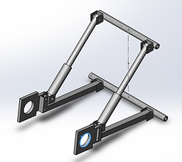
In the sketch shown below, the basic shape of the system is shown. The lower beams connect to the frame, motor, and dampening unit. This design iteration features a triangulated three-member system, with each member at an almost-equal length in the sprung (half-way loaded) position. The axle mounts, which are pre-made, need to have extra space for mounting at the rear. Additionally, a preexisting chain to connect the motor and axle could be used if necessary. The chain length would determine the place of the motor mounts and motor.
A second design iteration, featuring a fully contained one-piece EMPI coilover and a welded lower control arm was chosen to allow for a greater distance of travel and for practicality in availability of parts. Outsourcing the brackets and dampening units will also save in labor costs.
C)Benchmark
An application of similar layout is in three-wheeled motorcycles, much like the Can-Am Spyder vehicle (produced 2007-current) The rear of the Spyder uses a swing-arm-type suspension with a 145-mm shock. Due to design differences, the engine of such a vehicle is typically mounted underneath the driver. In the electric vehicle project, the layout is similar to a recumbent bicycle, with the driver in a laid-back position instead of upright. However, since the electric motor is to be suspended at the rear of the vehicle, there must be accommodations for the weight of the engine and driver. Additionally, since the vehicle is not completely designed and assembled, there must be assumptions made about the final weight of the vehicle.
D)Performance Predictions
Under these design calculations, the predicted performance is sustaining a load of approximately 300 lb (driver and vehicle) with the spring and shock compressed half-way allowing for a travel of 1.5 inches in either direction. If on-road testing is available, the suspension must keep the vehicle upright with no more than 5-degrees of tilt while cornering at 20 mph in a 40-foot radius.
After design revisions, the updated performance expectations are failure of a shock load of 700 lb to one given coilover. Anticipated vertical distance travelled at the center of the axle is calculated as 6.89 inches from full compression to full extension of the coilover unit.
E)Description of Analyses
The initial design was based on the following:
Making assumptions about the weight of the electric vehicle as a system at 300 lbs and setting arbitrary stationary lengths of 14 inches for each member allowed analysis to be performed.
Using basic geometry, the angle of the lower beam relative to the extended line of the vehicle frame was found – ideally varying from roughly 18 degrees to 43 degrees as it travels through its cycle of compression and extension. This will allow the driving engine to travel 1.5 inches in each direction from its neutral position (assuming the neutral position is with the spring half compressed). Knowing this, the length of the dampening unit needed to travel a minimum of 5.35 inches in order to accommodate the full compression of the spring.
Ideally, an exact dampening unit might be manufactured for this system. However, due to manufacturing costs, an aftermarket automotive “coilover” type shock assembly might be a suitable choice for both reliability and availability.
Using the spring equation, force = spring constant * displacement, it was determined that the spring constant was approximately 56 lb/inch. This is an “ideal” spring rate. Understandably, an automotive unit might be designed to accommodate a much larger sprung load. So, using a coilover spring with an adjustable perch would benefit the system in the scenario where the final weight of the vehicle is lighter/heavier than planned.
Design revisions were performed after finding a suitable pre-manufactured coilover shock. EMPI, an aftermarket Volkswagen parts manufacturer, produces a coilover shock for use on Dune-Buggy-type vehicles that fit the initial design figures after adjustments were made.
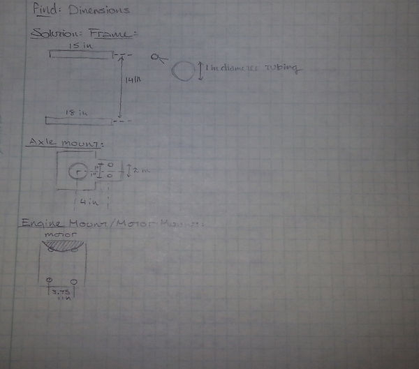
As demonstrated in the drawing below, the existing dimensions of components that were already manufactured played a large role in analysis and design. The existing frame, with the 14 inch bar spacing dictated the length of the lower control arm. This allows the control arm to operate in a coordinating semi-circle pattern.
With the goal of 3 inches of axle travel, a model was developed in Solidworks, a shock unit had to be found that would allow for adequate compression and extension – which results in the travel of the axle.
Stress calculations using various shapes of material and the failure load of the shock were performed in order to ensure that, under failure, the coilover will remain attached to the control arm and frame to allow for safety of the driver. Appendix A contains several cross sectional calculations to show stress in the lower control arm as a result of shock failure.
Appendix A features a full set of analytical sheets. After building a Solidworks model and adjusting the assembly to function using the commercially sourced parts, the final measurements and calculations were performed. The design was primarily Solidworks-centric, since a true analysis could not be performed until commercially sourced parts were found and documented. Using the commercial measurements, the model was adjusted.
F)Scope of Testing and Evaluation
The suspension will be tested in real world conditions – once the assembly is built and attached to the frame, a load test can be performed by simulating the weight of a driver and applying force to the frame externally. Since the final design iteration will make use of automotive shocks, the anticipated amount of suspension travel should be larger than the initial design allowed. If the vehicle is completed further before the end of the manufacturing of this project, then a road test can be performed to determine its ability to control the vehicle while cornering at race-pace speeds.
G)Analyses
i)Design Issue
The first design issue encountered was the ensuring that the dampening member of the system and the solid member holding the electric motor would not contact while the suspension travelled through its full path. As mentioned above, trigonometric and geometric equations were performed to calculate the predicted path of travel. Once the angles and lengths were calculated, the approximate spring rate needed for the dampening member was calculated.
A second potential design issue was the construction material for the lower control arm. The dimensions should remain similar, but minor adjustments may need to be made to accommodate use of the material that is available.
Finally, the system was adjusted and checked for accommodation of premanufactured parts (the EMPI coilovers, brackets, axle mounts, etc.)
ii)Calculated Parameters
Included below (and featured further in Appendix A) are some sample figures of parameters that were calculated.
Length of Control Arm.................................................................................... 14 inches
Compressed Length of Coilover................................................................. 11.25 inches
Extended Length of Coilover...................................................................... 16.75 inches
Horizontal Distance Travelled at Center of Axle............................................ 2.92 inches
Vertical Distance Travelled at Center of Axle................................................ 6.89 inches
Failure Load of Shock........................................................................................... 700 lb
The logic behind shear force applications, featured in Appendix A – 5, is explained below:
Since safety is paramount, fastening hardware had to have a much higher capacity than the rest of the components. The fastening hardware supplied with the Summit Racing Coilover Brackets is, as specified by the manufacturer, grade 5. Using shear force application, the minimum yield strength for the bolt is 92000 psi. By comparison, the failure of the coilover shock would be at 700 lb. If the entirety of this failure load was applied in shear against the bolt, it would produce 3565 psi. By having a large factor of safety, the failure should not be completely destructive.
Final calculations regarding travel distances were performed using both Soldiworks modeling and hand calculations, shown here from Appendix A – 12:
iii)Best Practices
As this suspension system is designed for an electric vehicle, it is of the utmost importance that safety for the driver is ensured. First and foremost, the suspension will be designed with a large factor of safety in mind. This is especially important, as the rest of the vehicle is still a work-in-progress, which may lead to the final weight of the vehicle being less or more than what was designed for currently. Additionally, sources of components that are commercially available will lead to easy maintenance and repair, should the vehicle need it. By staying ahead of maintenance, and making the system easy to repair, anticipated failures can be accounted for and minimized.
H)Device: Parts, Shapes, and Conformation
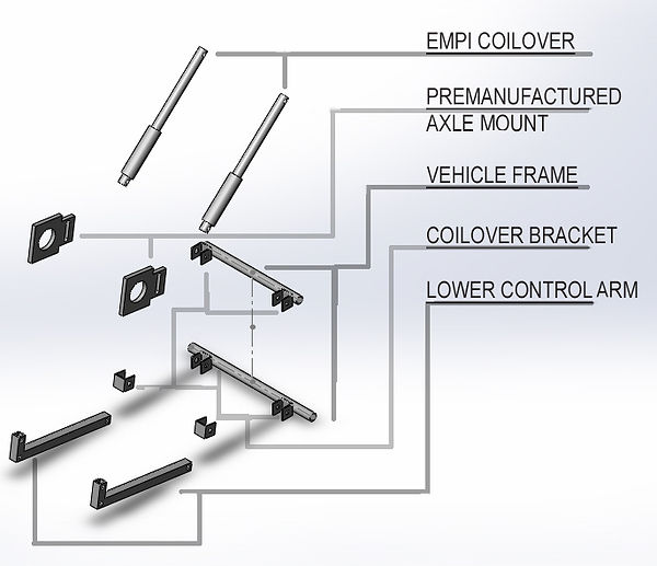
Part 001 – Lower Control Arms
These are the lower control arms that tie the dampening member to the frame and allow for suspension travel, in addition to holding the provisions for mounting the electric engine and axle mounts. There are two lower control arms in this system that remain parallel throughout the range of motion. Construction of the control arms is square steel tubing that is cut to length, notched, and welded. Specific points will then be drilled to allow for connections to brackets.
Part 002 – EMPI Volkswagen Dune Buggy One-Piece Coilover
These are the dampening members in the suspension system. They are produced by an aftermarket parts manufacturer and are designed for use in a dune-buggy-type vehicle. They are self-contained (one piece) coilovers. There is an adjustable ring on the unit itself that allows for some adjustability to pre-load the spring.
Part 003 – Summit Racing Coilover Brackets (Chassis Tab)
These are the provisions for mounting all the points in the system. These points, in specific, are the connection points between the lower control arm and the lower beam of the frame, the connections points between the lower control arm and the coilover, and the connection points between the coilover and the upper beam of the frame. These brackets include the fastening hardware.
Part 004 – Premanufactured Axle Mounts
These mounts were previously created for a different suspension setup for the electric vehicle project.
Per Electrathon America rules, there are no particular guidelines for suspension, and creativity is encouraged. More important than creativity, however, is safety. As such, the design and assembly of parts was carefully performed.
I)Device Assembly and Attachments
Once the parts have been manufactured and the required dampening components are purchased, the assembly is fairly straight forward. The coilover brackets (chassis tabs), provided by Summit Racing), will be welded to six points – 2 on the upper rail of the existing frame, 2 on the lower rail of the existing frame, and 2 on the lower control arms near the pre-made axle mounts. If there are clearance issues between the axle mount and brackets, the mounts can be modified slightly to ensure there are no fitment issues. The coilover units from EMPI will be bolted to the connection points at the frame and at the lower control arms. Then, the lower control arms will be bolted to the frame connection points on the lower rail. All the fasteners required will be included with the coilover brackets, which also supply bushings to prevent premature failure due to friction.
J)Tolerances, Kinematics, and Ergonomics
Several predesigned limitations exist based on the geometry of the frame. The lower member must be long enough to accommodate the axle and motor mounts. The distance between the upper and lower rear bars of the vehicle frame are previously set. Outside of these restrictions, the system has very few limitations. Since the suspension system is designed to have two arms, both must be identical in order to ensure that the rear of the vehicle remains true to the front.
K)Technical Risk Analysis, Failure Mode Analysis, Safety Factors, and Operation Limits
The safety factor for this design was featured in the initial design calculations, with an anticipated safe load of 300 lbs. By choosing to use automotive coilovers, the factor of safety is regulated by the manufacturer (for the weight of a full-size vehicle). The limit, provided by EMPI, is a load of 700 lbs per shock.
Ideally, the point of failure should be the coilover unit itself if it experiences an excessive force (caused by an accident or less-than-ideal conditions). The lower control arm and all mounting hardware should remain intact in the event of coilover failure, ensuring that the structural integrity of the system remains until the unit is able to be driven to a stop.


bottom of page